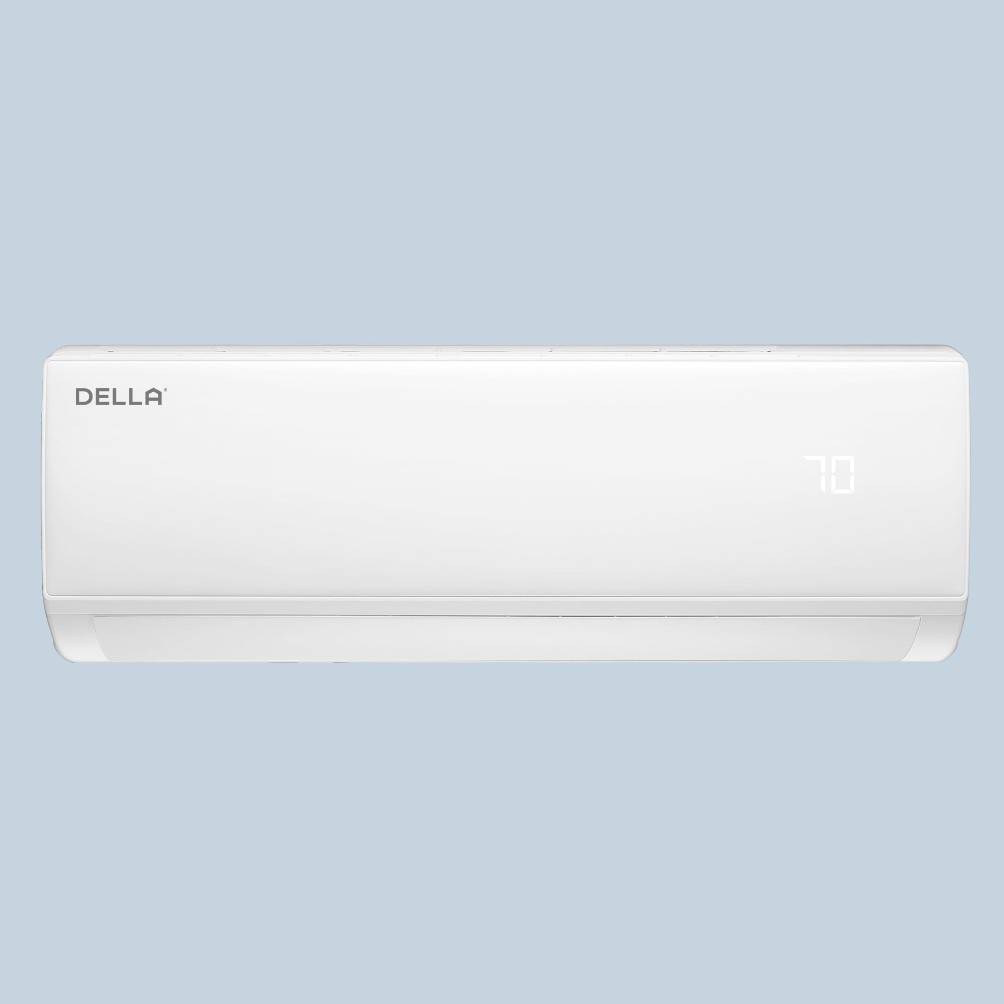
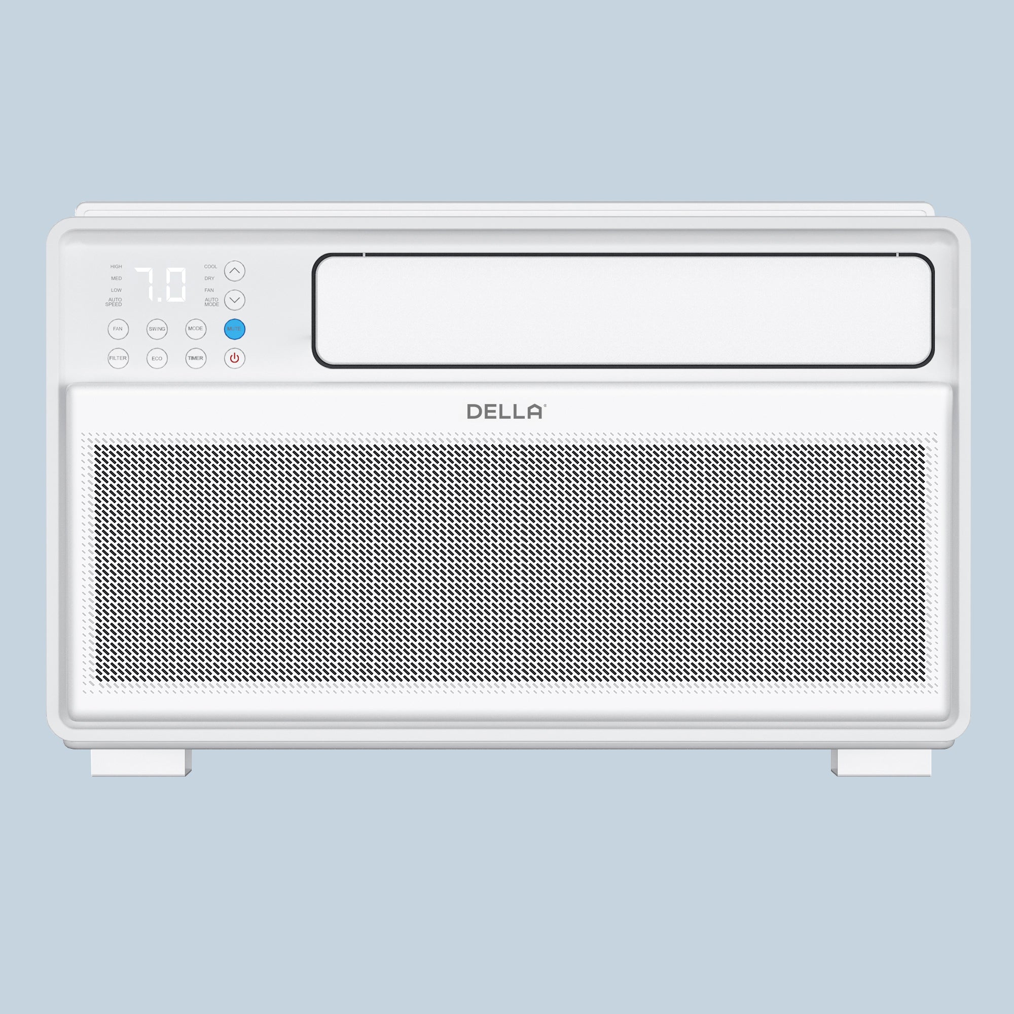
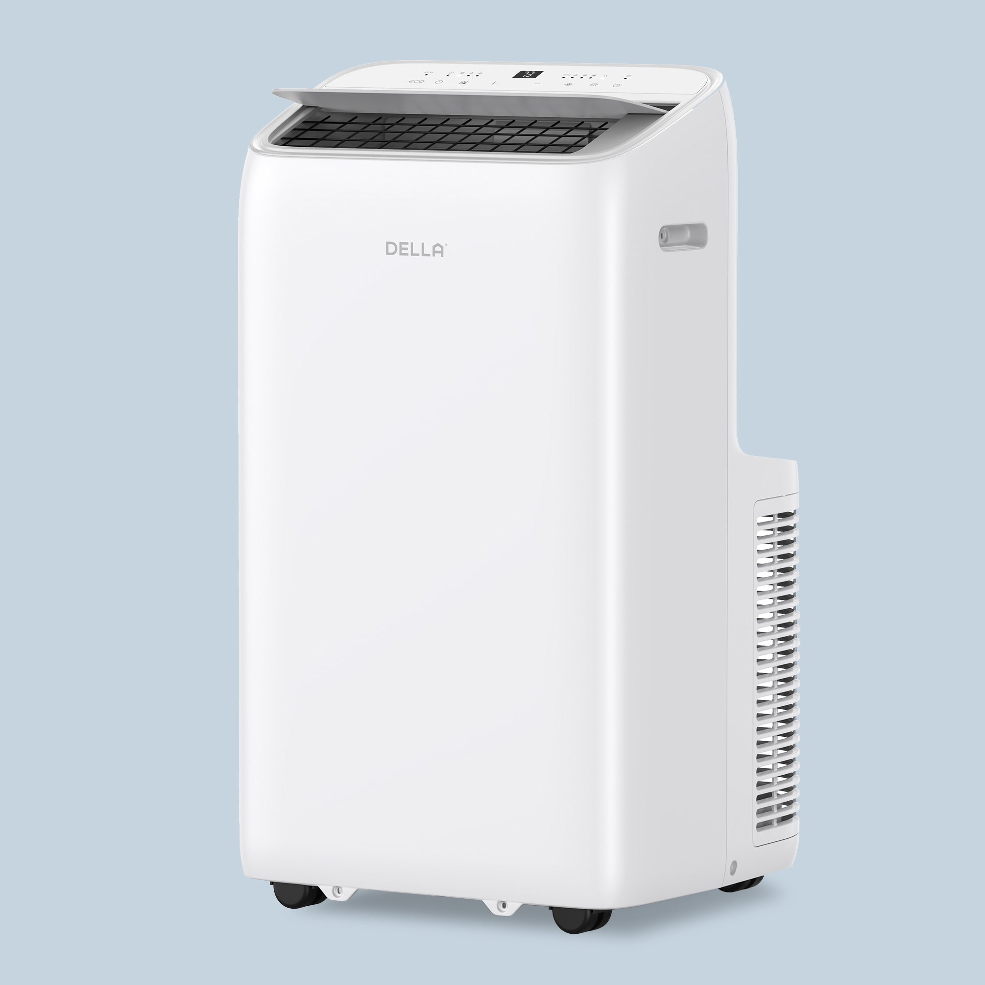
If you own a Della mini split system and suddenly see a strange code flashing on your display, don’t worry, you're not alone. These mini split error codes are designed to help you (and your technician) quickly pinpoint what’s going wrong. Whether it’s a simple sensor issue or a more complex problem like a communication failure between units, decoding these messages can save time, money, and frustration. In this guide, we’ll walk through the most common Della mini split error codes, explain what they mean in plain English, and give you a smart starting point for troubleshooting.
These error codes represent a wide array of potential issues within your Della mini split system, ranging from communication failures to sensor malfunctions and protection triggers.
After that, if you’re still confused, please don’t hesitate to call our customer service specialists at (800) 863-4143.
Single Zone Error Codes for Econo (IF) Series, Vario (TL) Series, Optima (TP) Series
For detailed troubleshooting steps, please refer to the PDF document linked below.
| Code | Reason |
| E0 | IDU & ODU Communication failure |
| E1 | IDU Room Temperature sensor failure. (IDU RT failure) |
| E2 | IDU Coil temperature sensor failure. (IDU IPT failure) |
| E3 | ODU Coil temperature sensor failure. (OPT) |
| E4 | AC Cooling system abnormal |
| E5 | IDU/ODU mismatched failure (specially performance test on the production line) |
| E6 | IDU PG Fan motor / DC fan motor works abnormal (IDU failure) |
| E7 | ODU Ambient Temperature sensor failure |
| E8 | ODU Discharge Temperature sensor failure. |
| E9 | IPM / Compressor driving control abnormal. |
| EA | ODU Current Test circuit failure |
| Eb | The Communication abnormal of Main PCB and Display board (IDU failure) |
| EC | ODU modules Communication failure |
| EE | ODU EEPROM failure. |
| EF | ODU DC fan motor failure. |
| EH | ODU suction temperature sensor failure |
| EP | ODU compressor casing top failure |
| EU | ODU Voltage test circuit abnormal. |
| Ej | ODU central coil temperature sensor failure. |
| En | ODU gas pipe temperature sensor failure. |
| Ey | ODU liquid pipe temperature sensor failure |
| P0 | IPM module protection. |
| P1 | Over / under voltage protection. |
| P2 | Over current protection. |
| P4 | ODU Discharge pipe Over temperature protection. |
| P5 | Sub-cooling protection on Cooling mode. |
| P6 | Overheating protection on Cooling mode. |
| P7 | Overheating protection on Heating mode. |
| P8 | Outdoor Over temperature/Under temperature protection. |
| P9 | Compressor driving protection (Load abnormal). |
| PA | Communication failure/mode conflict |
| F0 | Infrared Customer feeling test sensor failure. (IDU failure) |
| F1 | Electric Power test module failure. (IDU failure) |
| F2 | Discharge temperature sensor failure PROTECTION. |
| F3 | ODU coil temperature failure PROTECTION. |
| F4 | Cooling system gas flow abnormal PROTECTION. |
| F5 | PFC PROTECTION |
| F6 | The Compressor lack of phase / Anti-phase PROTECTION. |
| F7 | IPM Module temperature PROTECTION |
| F8 | 4-Way Value reversing abnormal. |
| F9 | The module temperature test circuit failure. |
| FA | The compressor Phase-current test circuit failure. |
| Fb | Limiting/Reducing frequency for Over load protection on Cooling/Heating mode. |
| FC | Limiting/Reducing frequency for High power consumption protection. |
| FE | Limiting/Reducing frequency for Module current protection (phase current of compressor). |
| FF | Limiting/Reducing frequency for Module temperature protection. |
| FH | Limiting/Reducing frequency for Compressor driving protection. |
| FP | Limiting/Reducing frequency for anti-condensation protection. |
| FU | Limiting/Reducing frequency for anti-frost protection. |
| Fj | Limiting/Reducing frequency for Discharge over temperature protection. |
| Fn | Limiting/Reducing frequency for ODU AC Current protection. |
| Fy | Gas leakage protection |
| bf | TVOC sensor failure (IDU failure, optional) |
| bc | PM2.5 sensor failure (IDU failure, optional) |
| bj | Humidity sensor failure. (IDU failure) |
| Fd | The communication of the refrigerant sensor is abnormal |
| Hd | Refrigerant Leak Protection |
| d4 | Water full protect |
| d5 | Access control protection |
| H1 | High pressure switch malfunction |
| H2 | Low pressure switch malfunction |
| CL | Filter duty remind |
Single Zone Error Codes for Motto (JA) Series Umbra (JPB) Series
For detailed troubleshooting steps, please refer to the PDF document linked below.
| Code | Reason |
| E0 | Overcurrent Protection of Indoor Unit |
| E1 | Indoor Unit temperature sensor error |
| E2 | Outdoor Unit coil sensor error |
| E3 | Indoor Unit coil sensor error |
| E4 | Indoor Unit motor error of wall mounted air conditioner (PG motor) |
| E4 | Indoor Unit motor error of wall mounted air conditioner (DC motor) |
| E5(5E) | Indoor Unit and Outdoor Unit communication error |
| Eb | Indoor EE Failure |
| F0 | Outdoor Unit DC motor error (3-core terminal motor) |
| F1 | Module protection error |
| F2 | PFC protection error |
| F3 | Compressor startup error |
| F4 | Discharge sensor error |
| F5 | Compressor top head sensor error |
| F6 | Outdoor Unit temperature sensor error |
| F7 | OVP or UVP error |
| F8 | Outdoor Unit main PCB and module panel communication error |
| F9 | Outdoor EE error |
| FA | Recirculated sensor error (four-way valve switch error) |
| P2 | High-pressure protection( only floor standing) |
| P3 | Liquid Deficiency Protection |
| P4 | Refrigeration Overload Protection |
| P5 | Discharge Protection |
| P6 | Indoor High Temperature Protection |
| P7 | Anti-freezing Protection in Refrigeration Room |
| P8 | Overcurrent Protection |
| L0 | DC Over/Under-voltage Failure |
| L1 | Overcurrent Protection on Phase Current of Compressor |
| L2 | Out-of Step Failure of Compressor |
| L3 | Phase Failure of Compressor |
| L4 | Driver Module IPM Failure of Compressor |
| L5 | PFC Overcurrent Hardware Protection |
| L6 | PFC Overcurrent Software Protection |
| L7 | AD Abnormal Protection in Current Detection |
| LC | AD Abnormal Protection in PFC Current Detection |
| Ld | Dc fan motor detection AD abnormal protection |
| L8 | Shunt Resistance Imbalance Failure |
| L9 | IPM Temperature Sensor Failure |
| LA | Compressor Startup Failure |
| LE | DC fan motor phase error |
| LF | DC fan motor lost step protection |
| LH | DC fan motor IPM protection |
Error Codes for Multi-Zone
For detailed troubleshooting steps, please refer to the PDF document linked below.
| Code | Reason |
| E0 | IDU & ODU Communication failure |
| E1 | IDU Room Temperature sensor failure. (IDU RT failure) |
| E2 | IDU Coil temperature sensor failure. (IDU IPT failure) |
| E3 | ODU Coil temperature sensor failure. (OPT) |
| E4 | AC Cooling system abnormal |
| E5 | IDU/ODU mismatched failure (specially performance test on the production line) |
| E6 | IDU PG Fan motor / DC fan motor works abnormal (IDU failure) |
| E7 | ODU Ambient Temperature sensor failure |
| E8 | ODU Discharge Temperature sensor failure. |
| E9 | IPM / Compressor driving control abnormal. |
| EA | ODU Current Test circuit failure |
| Eb | The Communication abnormal of Main PCB and Display board (IDU failure) |
| EC | ODU modules Communication failure |
| EE | ODU EEPROM failure. |
| EF | ODU DC fan motor failure. |
| EH | ODU suction temperature sensor failure |
| EP | ODU compressor casing top failure |
| EU | ODU Voltage test circuit abnormal. |
| EJ | ODU central coil temperature sensor failure |
| En | ODU gas pipe temperature sensor failure. |
| Ey | ODU liquid pipe temperature sensor failure |
| P0 | IPM module protection. |
| P1 | Over / under voltage protection. |
| P2 | Over current protection. |
| P4 | ODU Discharge pipe Over temperature protection. |
| P5 | Sub-cooling protection on Cooling mode. |
| P6 | Overheating protection on Cooling mode. |
| P7 | Overheating protection on Heating mode. |
| P8 | Outdoor Over temperature/Under temperature protection. |
| P9 | Compressor driving protection (Load abnormal). |
| PA | Communication failure/mode conflict |
| F0 | Infrared Customer feeling test sensor failure. (IDU failure) |
| F1 | Electric Power test module failure. (IDU failure) |
| F2 | Discharge temperature sensor failure PROTECTION. |
| F3 | ODU coil temperature failure PROTECTION. |
| F4 | Cooling system gas flow abnormal PROTECTION. |
| F5 | PFC PROTECTION |
| F6 | The Compressor lack of phase / Anti-phase PROTECTION. |
| F7 | IPM Module temperature PROTECTION |
| F8 | 4-Way Value reversing abnormal. |
| F9 | The module temperature test circuit failure. |
| FA | The compressor Phase-current test circuit failure. |
| Fb | Limiting/Reducing frequency for Over load protection on Cooling/Heating mode. |
| FC | Limiting/Reducing frequency for High power consumption protection. |
| FE | Limiting/Reducing frequency for Module current protection (phase current of compressor). |
| FF | Limiting/Reducing frequency for Module temperature protection. |
| FH | Limiting/Reducing frequency for Compressor driving protection. |
| FP | Limiting/Reducing frequency for anti-condensation protection. |
| FU | Limiting/Reducing frequency for anti-frost protection. |
| FJ | Limiting/Reducing frequency for Discharge over temperature protection. |
| Fn | Limiting/Reducing frequency for ODU AC Current protection. |
| Fy | Gas leakage protection. |
| bf | TVOC sensor failure (IDU failure, optional) |
| bc | PM2.5 sensor failure (IDU failure, optional) |
| bj | Humidity sensor failure. (IDU failure) |
| Fd | The communication of the refrigerant sensor is abnormal |
| Hd | Refrigerant Leak Protection |
| d4 | Water full protect |
| d5 | Access control protection |
| H1 | High pressure switch malfunction |
| H2 | Low pressure switch malfunction |
| CL | Filter duty remind |
Note: If these tips appear when the air conditioner is used, it does not mean that The air conditioner is faulty, but only a reminder of the function operation.
| Number | Code | Introduction |
| 1 | CL | Filter fouling reminder function |
| 2 | AC | SELF-CLEAN function |
| 3 | 0A | In the GEN function, that the current value of the corresponding gear of the outdoor has not been sensed. |
| 4 | *A | In the GEN function, the current value is limited to * amps ( "*"indicates the numbers 1 to 20 ) . |
| 5 | 0F | Display sign "off" when GEN function is off. |
| 6 | CF | WIFI preset: Waiting network. |
| 7 | PP | WIFI preset: Searching the router. |
| 8 | SA | WIFI preset: connected to the router. |
| 9 | AP | WIFI preset: connected to the server/ AP mode: Waiting network. |
| 10 | D* | DRED function (Three gears: D1/D2/D3) |
Your Della Mini Split Error Codes and Smart Home
In short, getting to know your Della mini split error codes is like having a secret map to a smoother, stress-free system. Once you’ve cracked the code, you’ll be ready to troubleshoot and resolve those little hiccups, keeping your home at that perfect “just right” temperature all year long. But why stop there? If you're looking to level up your comfort, take a look at Della’s full range of industry-leading mini splits, portable ACs, window ACs, and tower fans. Plus, don’t forget to check out our socials and blog for loads of handy tips, insights, and tutorial videos that will help you create your ideal home environment. Stay cool, stay in the know, and let Della keep you comfortable every step of the way!
Get dialed in with Della today!


LEAVE A COMMENT
All comments are moderated before being published.
This site is protected by hCaptcha and the hCaptcha Privacy Policy and Terms of Service apply.